Tail Pipes
The only visible part of the Exhaust System on
a vehicle. This produces a final reduction in pressure, and sometimes used to
enhance the appearance of the car. All of our Stainless Steel exhaust tips are
manufactured from 100% 304 Stainless Steel. 304 Stainless Steel is the highest
quality Stainless Steel and retains its high luster polish longer than any
other material.
l Polished 304 Stainless Steel Tail Pipes
l Chromed Tips
l Black coated Tips
l Blue Plated tips
l Stacks
l Tail Pipes With Single or Double Wall
construction
l Square tips
l Dual outlet tips
Tail Pipe Tail Pipe,Dual Tail Pipes,Muffler Tail Pipe,Exhaust Tail Pipe JINING FAREAST LIANGFEI CONVERTER & MUFFLER CO. LTD , http://www.liangfeiexhaust.com
0 Introduction In 1999, according to the reform plan of the State Power Corporation, the former Northeast Electricity Group was reorganized into the Northeast Corporation of the State Power Corporation and the three provincial power companies in Liaoning, Jilin and Heihe. Correspondingly, the dispatching system of the northeastern power grid has also undergone changes. The transformation from the original dispatch within the large power grid to the tie-line dispatch has taken priority. In order to maintain the frequency stability of the power grid under the new dispatching system of the Northeast Power Grid, the three provinces of Northeast China and Northeastern China implemented a real-time monitoring project for the junction line power, namely, regional deviation control (ACE). According to the fact that the northeastern power grid system is compact in structure and closely connected with other power plants, it is very suitable to adopt frequency deviation adjustment. Its purpose is to: 1 Provide real-time power monitoring means for daily dispatch operations, including total delivery and total power monitoring by provincial companies. Each company communicates real-time power monitoring. The network dispatch and provincial dispatcher shall adjust the generator load within the jurisdiction of the real-time power monitoring system to ensure that the entire day's liaison line passes, the received power plan and the unit daily power generation plan are successfully completed. 2 Provides consistent power generation control deviation data for AGCs of 3 provincial control centers to ensure that the control commands of the entire control center are coordinated with each other, thereby ensuring the target of frequency control of the entire network and the real-time control target of the junction line power. (See Northeast China Power Grid Dispatch and Communication Center, "The Measures for the Northeast China Power Grid Province, Interconnection Line Electricity, Electricity Transaction and Settlement Measures" and "Northeast Power Grid Dispatch Operation Management Regulations", 1999).
This article will introduce the design and implementation of a real-time monitoring and control system for the junction gateway dispatching jointly developed by the Northeastern Power Grid Dispatching Center and the China Electric Power Research Institute.
1 The characteristics of the real-time monitoring system of the junction gateway dispatching control The real-time monitoring system of the real-time gateway dispatching system is actually a geographically distributed monitoring system. The monitoring center is located in the Northeast Company of the State Power Corporation, and the control is located in the three provinces of Liao, Ji, and Hei. The AGC implementation. Therefore, the real-time monitoring system for tie line dispatch consists of tie line power plan management, real-time data collection, real-time information release, and monitoring man-machine system. Has the following main features:
a. The system structure design is implemented based on the existing configuration of dispatching and control center dispatching automation system as a basic structure, and no additional equipment is required. The network dispatching automation system is the hub of telecontrol information for the entire region, and is responsible for the collection of power data. The power monitoring data is distributed to the three provinces in Northeast China through the real-time power communication function; the dispatch automation systems of each province are responsible for receiving and dispatching Curve data, based on the real-time data drawing schedule monitoring curve, on the other hand, the ACE data of the control center is transmitted to the center's AGC system to implement the real-time control of the power line deviation of the tie line gate.
b. The man-machine interface provides various types of monitoring curves, quick calling of each company's curve, and mutual switching functions; the curve can provide various time ratio coordinates for overall monitoring and local monitoring of the curve. The density of the curve points is one point per 5 s; It can automatically scroll forward over time for scheduling monitoring.
c. The power monitoring curve can be adapted to any real-time modification of the gate power plan. Do track the current plan curve.
d. Make full use of the measured data at both ends of the tie line to filter out the effects of abnormal data (dead or jump) on the curve.
2 Main Algorithms The main algorithm of the junction gateway dispatching real-time monitoring system includes three: 1 network processing data processing algorithm for data collection; 2 linear splitting algorithm for planned values; and 3 regional active difference algorithm [1].
2.1 The data processing algorithm of the connection line at the network end The calculation of the gateway power of each company is calculated from the transmission power value of each connection line. According to the principle of power assessment of the gateway, the selection of the power data should be collected at the transmission end. The data arrived is accurate, but due to the objective reasons of various aspects, such as poor running stability of the RTU equipment and insufficient reliability of the channel, there will be a problem of inaccurate power measurement. In order to improve the continuous availability of the gate power monitoring curve, the data at the end and end of the line must be used to determine the high-reliability line power value. When the data at one end is abnormal, or the data at the head end is inconsistent, reliable data can be obtained. Electricity calculation.
The method of determining the power value for each connection line is as follows. 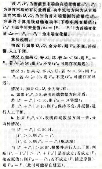
Relevant basic principles: Counting, alarming, and manual intervention can only be done when certain problems are identified; once the PM does not change, manual intervention can be used to restore it. Counting function requirements: The function of counting and clearing numbers is relatively independent and accurate (50 alarms after). Alarm, manual intervention function requirements: there is voice prompt, pop-up dialog box, prompt line name and the measured value and PM value at both ends of the line, and the cause of the alarm; the dialog box has manual intervention function, that is, the dispatcher can manually confirm which end of the PM is used Measured value or manual input, the value can be returned to the program, PM will automatically use this value in the next cycle, until the case of clear count in the program, using the value automatically confirmed in the program.
2.2 plan value of the linear split algorithm a. First of all, get the last point of the previous day's plan value, because at the time of splitting 96 points (15 minutes for a planning point, a total of 96 points a day) plan value will use the last point of the previous day plan value.
b. Then take the 96-point plan value of the day, together with the last point of the previous day and the first point of the previous day, totaling 98 points.
c. By linear split method:
Interval value = [value] - value(i)]/180 where i represents a certain point of the 96-point plan value. The formula shows that the planned value of the previous point minus the planned value of the later point is divided by 180 to obtain the 5s interval value.
The value of a certain point in a certain period (1~180) = value(i) + interval value × time point (1~180)
The formula indicates that the planned value of a certain point in a real-time database in a certain period is a certain point in 96 points plus the interval value multiplied by the position of the point (Note: - 96 points per day, plus the last point and the next day of the previous day The first point is a total of 98 points. The real-time database has one point every 5 seconds and a total of 180 points in 15 minutes, that is, the points that are separated by 180 real-time databases in the two planned values).
d. If the dispatcher needs it, calculate the schedule of the next day in the same way.
2.3 Regional active difference algorithm The regional active difference algorithm is relatively simple. That is, the active difference between the network adjustment, Liaoning, Jilin and Heilongjiang is based on the real-time monitoring program of the gateway power from the telemetry table of the SCADA real-time database. The physical numbers of the four regions are taken out of the active values ​​of each region, and the planned values ​​that are completed by linear splitting and stored in the real-time database of the link are subtracted. In order to ensure the accuracy of the gate scheduling, the real-time monitoring program of the gateway power is sampled every 5s. Calculated as follows:
Regional active power difference = regional active power - regional planning value 3 Conclusion In order to achieve the tie-line dispatch model under the new system, the China Electric Power Research Institute and the Northeast Power Network jointly developed the Northeast Power Grid tie-line dispatch real-time monitoring system. , And officially launched in May 2000, has been running for 1 year. Practice has proved that this system provides effective and rapid management tools and technical guarantees for the safe and economical operation of the power grid under the new dispatching system.
Abstract : In order to adapt to the new dispatching system of the Northeast Power Grid, a real-time monitoring system for the junction control of the tie line was developed. The design principles and components of the system are introduced. The main algorithms for identifying and correcting bad data, interpolating between tie-line plans, and calculating regional control deviations are discussed. One end of the real jump, the other end of the same time, or long-term power imbalance caused by the gradual change will alarm.