Waste Tyre Recycling Machine can process varities waste rubber production: Waste car tyre, waste truck tyre and other different waste tyre, waste rubber, waste cabel and other waste rubber productions. End production will be tyre pyrolysis oil, carbon black, steel wire, whole working process is full sealed and eco-friendly. Achieve the Goal that converting waste to energy.
Accoring its working type, we have 3 designs: Batch type, semi-continuous and continuous.
Waste Tyre Recycling Machine Waste Tyre Recycling Machine,Waste Tyre Recycling Machine With New Patent Shangqiu Yilong Machinery Equipment Co., Ltd. , http://www.pyrolysis-equipment.com
SOE is the abbreviation of SEQUENCE OF EVENTS. Its meaning is the accident sequence record, that is, the accident recall system in every power plant. In the power plant, it is an important basis for finding the cause of the accident and analyzing the equipment failure. Sanhe Power Generation Co., Ltd.'s DCS system software and hardware are provided by the United States MCS company. Since the accident recall system has been put into production, after several tests and accident record inspections, the sequence of certain records appears inconsistent with the actual sequence of actions, which has seriously affected the search and analysis of the causes of the accident. Through experiments and discussions with foreign experts to find out the reasons for inaccurate records, and using the opportunities of thermal control professionals of #2 machine minor repair in September 2001 to complete the transformation of the SOE system. The effect of the retrofit was tested by the #2 machine start-up test. The test results confirmed that the reform was successful and the SOE record was completely correct. 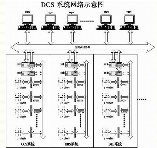
2. Explanation of terms:
SOE: SEQUENCE OF EVENTS - accident sequence records
DPU: DISTRIBUTED PROSESSING UNIT - Distributed Processing Unit
DBM: DATA BUS MODULE - Data Bus Module
CCS: COORDINATED CONTROL SYSTEM - Coordinated Control System
BMS: BURNING MANAGE SYSTEM-Combustion Management System
DAS:DATA ACQUISITION SYSTEM-Data Acquisition System
SCS: SEQUENCE CONTROL SYSTEM - Sequential Control System
48VDI card: 48VDC power supply, external card input for dry node
BCM card: Binary control module, providing 48VDC power supply, external card input for dry node, different wiring mode than 48VDI card.
DIB: DIGITAL INPUT BUFFER - Digital input buffer data block.
DTB: DIGITAL TERMINAL BUFFER - Data block with digital input DIB as SOE
3. Introduction of SOE System of Sanhe Power Plant SOE system software of Sanhe Power Plant is provided by MCS, USA; software version: MAX1000+PLUS1.4.3; 177 points of SOE system currently entering Sanhe Power Plant are DAS of DCS system. 84 points) Subsystem, SCS (57 points) subsystem, CCS (9-point) subsystem, BMS (27-point) subsystem; resolution of SOE record is specified as 1ms.
The SOE system is composed as shown in the figure: 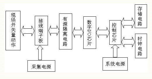
4, the reasons for the transformation
4.1. Analyze the SOE record when the #2 starter trip test on September 5, 2000
05/Sep/00 05:36:41.826 SQ 2CJA01COA04 DRUM LEVEL LOW
Drum level is low
05/Sep/00 05:38:12.842 SQ 2CJA01COA04 DRUM LEVEL LOW
Drum level is low
05/Sep/00 05:41:15.409 SQ 2CJA01COA03 DRUM LEVEL HIGH
Drum level is high
05/Sep/00 05:41:41.529 SQ 2CJA01COA03 DRUM LEVEL HIGH
Drum level is high
05/Sep/00 05:44:56.081 SQ 2CJA01COA03 DRUM LEVEL HIGH
Drum level is high
05/Sep/00 05:46:22.473 SQ 2CJA01COA03 DRUM LEVEL HIGH
Drum level is high
05/Sep/00 05:49:31.641 SQ 2CJA01COA03 DRUM LEVEL HIGH
Drum level is high
05/Sep/00 05:50:23.828 SQ 2CAA10CB015 TBN AUTO STOP OIL PRESS LOW TRIP
Turbine Automatic Shutdown Low Oil Pressure Trip
05/Sep/00 05:50:23.964 SQ 2CAA10CB022 TBN EMGCY TBN TRIP PB ON
The emergency trip button of the steam turbine can be seen from the above record: Before the “Turning machine emergency trip button press†signal appears, the “auto turbine shutdown oil pressure low trip†signal has been issued. This is not in line with the equipment's operation sequence. .
4.2. Analysis of the SOE record of the accident shutdown of #2 machine on September 14, 2000
14/Sep/00 03:17:02.322 SQ 2HLB20CBM03 FDF B PROT ACT
Blower B protection
14/Sep/00 03:17:02.350 SQ 2HLB10CBM03 FDF A PROT ACT
Blower A protection
14/Sep/00 03:17:23.481 SQ 2HNC30CBM03 IDF A PROT ACT (HIGH SPD)
Induced fan A protection action (high speed)
14/Sep/00 03:17:50.105 SQ 2HNC10CBM03 IDF A PROT ACT (LOW SPD)
Induced fan A protection action (low speed)
14/Sep/00 03:17:54.237 SQ 2HNC40CBM03 IDF B PROT ACT (HIGH SPD)
Draft fan B protection action (high speed)
14/Sep/00 03:18:12.019 SQ 2HLB10CBM03 FDF A PROT ACT
Blower A protection
14/Sep/00 03:18:18.009 SQ 2HLB10CBM03 FDF A PROT ACT
Blower A protection
14/Sep/00 03:18:21.355 SQ 2HFE10CBK01 PAF A MTR STOPPED
A fan A motor stopped
14/Sep/00 03:18:21.392 SQ 2HFE20CBK01 PAF B MTR STOPPED
One fan B motor stopped
14/Sep/00 03:18:21.626 SQ 2CAA10CB015 TBN AUTO STOP OIL PRESS LOW TRIP
Turbine Automatic Shutdown Low Oil Pressure Trip
14/Sep/00 03:18:21.735 SQ 2CAA01C0011 UNSTABLE FIRING CONDITION
Unstable combustion
14/Sep/00 03:18:21.797 SQ 2CAA01C0001 MFT
Main fuel tripping
14/Sep/00 03:18:21.841 SQ 2HFC20CBK01 PULVB MTR STOPPED
Coal mill B motor stopped
14/Sep/00 03:18:21.962 SQ 2CAA01C0022 TURBINE TRIP
Steam turbine trip
14/Sep/00 03:18:22.378 SQ 2HHA10Z1120 PULVB BNR_1 SO DMPR OPEN SOE
Coal mill B#1 burner shut off
14/Sep/00 03:18:22.638 SQ 2CAA10CB021 TBN VLV FULL CL
The turbine valve is fully closed and the accident is stopped as a "fire escape." From this record, it can be seen that before the "MFT" signal appears, the signal "The turbine is automatically stopped and the oil pressure is low" has been issued. This is not in line with the order of operation of the equipment.
The SOE record order of #2 machine is inconsistent with the sequence of events. This seriously affects the analysis and judgment of the accident. After researching with the technical personnel of MCS, it is decided that the SOE system will be reconstructed, and the basic reconstruction program and equipment will be provided by MCS.
5, the reason analysis
SOE acquisition schematic diagram: 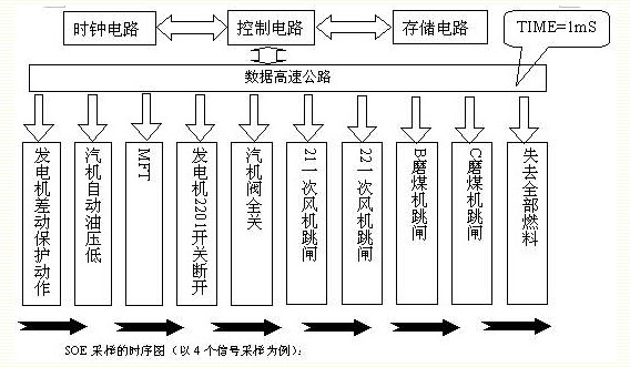
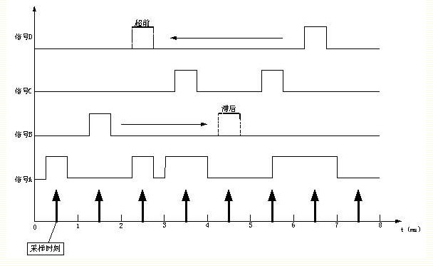
According to the DCS system network diagram and SOE sampling timing diagram to analyze the reasons for inaccurate SOE records (assuming that the signal belongs to the CCS system, the signal belongs to the SCS system, the signal C and D belong to the DAS system DPU32 and DPU34): DCS system network The DBM and DPU have their own clocks. The DBM clock of one of the subsystems is used as the reference in the system. The clock requirements of other devices are synchronized with the reference clock. If the DBM (data bus module - used to manage the data transmission of the DPUs of each subsystem and the communication with the host computer) of each subsystem is fully synchronized with the DPU clock inside the subsystem, the signal sequence of the SOE record should be A → B → C → D; if the DBM clock of the SCS system is faster than 3ms when other system clocks are synchronized, the SOE system will collect the signals according to their system time and generate the recording order as A→C→B. →D; if the DBM clock of the entire system is synchronized and the DPU34 clock of the DAS system is 4ms slower than the DPU32, then the SOE system will collect the signals according to the DPU time when the sequence is A→B→D→C . The main reason for this is due to the fact that designers do not understand the details of the system equipment and do not take into account the problem of clock synchronization between different subsystems and between different DPUs in the same subsystem. SOE points are allocated differently. Management in the subsystem.
6. The overall scheme of the transformation: add an SOE cabinet to the DAS system, and connect the SOE points of the used systems to the cabinet in a hard-wired manner. The same DPU under the same subsystem manages and is controlled by the same sampling clock. . This avoids the problem of clock out-of-sync between different subsystems and among different DPUs in the same subsystem, ensuring that the sampling order is in line with the actual operation sequence of the device.
6.1 The layout of the card layout in the layout cabinet of the SOE cabinet is the definition of the address and the system to which it belongs as shown in the figure: 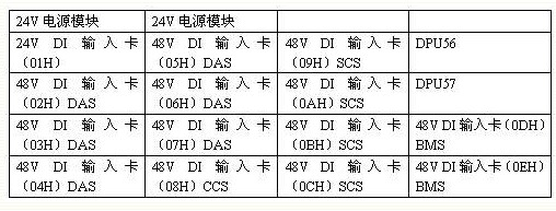
Note: The 24V DI input card is used for 24V power monitoring. In order to facilitate the discharge of the cable, two steel pipes are fixed below each piece of card to bind the cable.
6.2, the connection of the power cable
6.2.1, 220V power cable connection Between the DCS power cabinet and the SOE cabinet, put three three-core cables through the cable sandwich, two of which are connected to the 28 and 30 switches of the #1 DCS power cabinet as the one-way power supply of the SOE cabinet. Cabinet fan power; another 26 switch connected to the #2DCS power cabinet serves as the other power source for the SOE cabinet.
6.2.2. 24V Power Cabinet The 24V power supply for all the cards is provided by two 24V power modules inserted on the top.
6.2.3. Connection of 48V Power Cables According to the design, the 48V power supply of CCS system, SCS system, DAS system and BMS system are respectively led to the SOE cabinet. The connection of the 48V power supply has connected the common signal lines of the 48V DI card together, and only another signal line can be connected when connecting the signal cable, which greatly reduces the number of signal cables used.
6.2.4 Ground Cable Connection
The SOE cabinet is connected to the DAS system cabinet ground through a 7mm single-core cable, and the specific location is in the DAS system #1 cabinet.
The 24V "-" pole of the SOE cabinet is connected to the 24V "-" pole of the DAS system through a 7mm single core cable, and the specific location is in the DAS system #1 cabinet.
6.3. SOE retrofit project point statistics and use of cables
#2 machine SOE total 177 points, 51 cables laid out are as follows: 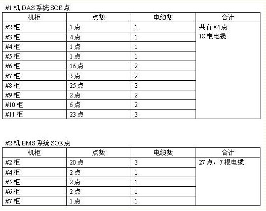
6.4, Signal Connection Mode The design principle of this scheme is that the signal points of the same card of SOE cabinet come from the same DCS subsystem. The connection mode is: the signal is output from the original signal terminal and connected to the SOE card. The arrangement in the SOE cabinet is that the clips are from top to bottom and the cables are arranged from inside to outside.
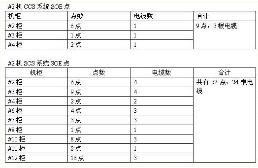
48V DI signal point - 48V DI input card as shown: 
BCM card signal point and 48V DI card signal point send --- SOE cabinet 48V DI input card, that is, in the original design for the BCM card wiring terminals inserted 48V DI card signal point input (this item is not part of the original design) 
Description: Press the above diagram to connect the 1 channel (left) connection of the 48V DI card to the 48V DI input card (right) designed as the BCM connection. First cut off the short-circuit bar connected to the 34 terminal, and then connect the 48V "+" (40-pin PS COM in the figure) to the 34-terminal with a short wire, and finally connect the signal line from the 2 terminal of the original 48V DI input card. 33 terminals. The signal loop is: 34 terminals (48V of "+") → internal loop of the card (RRS in the diagram) → 33 terminals → 2 terminals (left) → external nodes → 2 terminals (left) → 48V of "-" (left ) PS COM. This design fully meets the needs of signal transmission.
The BCM card signal and the 48V DI card signal are sent to the 48V DI input card of the SOE cabinet at the same time. That is, the BCM card signal point input is inserted in the terminal originally designed for wiring the 48V DI card (this item is not part of the original design). 
Note: As an example, follow the diagram above to connect the 2-channel (left) wiring of the BCM card to the 48V DI input card (right) designed as a 48V DI wiring. First cut off the short-circuit bar connected to the 32-terminal, and then connect the 48V "-" (40-pin PS COM in the figure) to the 32-terminal with a short wire, and finally connect the signal wire from the 3 terminal of the original BCM card to the 33 terminal. . The signal loop is: left 2 terminals (48V "+") → external node → 3 terminals → 33 terminals (right) → internal loop of the card (RRS in the figure) → 32 terminals (right) → 48V "-" ( Right) PS COM. This design fully meets the needs of signal transmission.
6.5. Connection of Communication Cables The 9.5m cable jacket protective steel pipe is installed between the SOE cabinet and the DAS system #1 cabinet. Four SOE communication lines are sent through the steel pipe to the DAS system #1 cabinet, and the OEI and DAS32 DPUs are connected. The communication line is unlocked, and the DPU communication line of the SOE cabinet is serially connected to it, and is defined as DAS56 and DAS57 to complete the communication connection.
7, system debugging method shown in Figure: 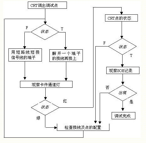
8, the problems encountered in the transformation process and treatment methods
8.1. The status of the indicator lights of some 48V card channels after power transmission is incorrect, and the voltage is not within the specified range. Solution: After inspection, it is found that the 48V "-" of each subsystem is not at the same potential difference, and each subsystem is The 48V "-" polarity short circuit is shorted together to eliminate the potential difference between the "-" poles of the 48V and the system returns to normal.
8.2. The battery of the SOE auxiliary DPU cannot be charged properly. Solution: After inspection, it is found that the battery is normal, and the DPU card itself has a problem and replace the DPU.
8.3, DTB points in the database can not be downloaded to the secondary DPU
Solution: Reset the communication alarm of the DPU, then download it and get success.
8.4, card 24V status light flashing solution: Define the corresponding DIB in the database to download the card communication is normal.
8.5. To simplify the SOE system and make the SOE system more secure, in this SOE-improved system, the SOE signal of the DC 110V voltage level (signal mainly from the electrical system) does not enter the dedicated SOE cabinet, but is in the original The DAS system completes the SOE signal.
9. Effect after transformation In order to compare the effects of SOE, with the original SOE point reserved, the results of the SOE recording were as follows: #2 machine started the test on September 16, 2001. 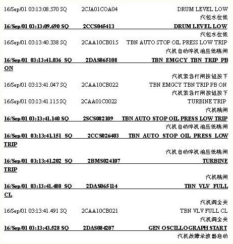
Note: Records with underlined SOE records after renovation, and other records before modification are still in the following sequence: Drum low water level → Steam turbine emergency trip button press down → Turbine automatic shutdown Oil pressure low tripping → Turbine tripping → Steam turbine valve Fully closed → Steam Turbine Fault Recorder is started. This record sequence is in the order of the actual operation of the equipment. The order of recording after retrofit is: low drum water level → automatic shutdown of turbine engine oil pressure low tripping → turbine emergency trip button press down → turbine tripping → turbine valve closing → turbine fault recorder activation. This record sequence and actual operation of the equipment The order is completely consistent and confirmed by the operating personnel. The part that has so far experienced problems has returned to normal.
1 Introduction