Modular sanding station can be widely used in 3c electronic products, household and sanitary ware, traffic and transportation, auto parts accessories, aerospace workpiece and millling workpiece precision fields.It has all the characters of Force Control System, or active contact flange, Constant Force Actuator---flexible control, quick reponse, instant adjusting. Modular sanding station, sanding force control system, sanding active contact flange, sanding constant force actuator DARU Technology (Suzhou) Co., Ltd. , https://www.darudfc.com
Keywords: double-flow heat meter, flow measurement technology, non-magnetic type 1. Introduction China's heat meter technology has a big gap compared to foreign advanced level. From the status quo of the integrator, flow sensor and temperature measurement technology of three important components of the domestic heat meter, due to the use of imported microprocessors, the related problems of the integrator have been better resolved. Temperature measurement using more mature technology PT1000 platinum resistance, but also a better solution. The current problem is more flow measurement part, the domestic heat meter base table uses the original hot water meter, its measurement accuracy and reliability is difficult to meet the flow meter technical requirements, so the development of high precision, reliable thermal table , is an important issue in the development of heat meters. This article analyzes and discusses the technical problems of the heat flow table beam table, and proposes a new method of adjusting the equivalent pulse by setting the “flow guiding sheet†shunt and the top cover of the impeller chamber to “adjust the ribsâ€, and obtains very good results.
2. The technical scheme of single stream beam table design The traditional single stream beam table structure is shown in Fig. 1. To ensure that the impeller rotates in a certain direction, its inlet and outlet ports are often eccentrically set and set at certain locations. The equivalent pulse adjustment unit. This structure has the following drawbacks. Firstly, the eccentricity of the inlet and outlet ports creates a certain degree of difficulty for machining. When machining the inlet and outlet ports, the setting of eccentricity brings inconvenience to the installation and alignment of the workpiece. It is time-consuming and labor-consuming and inefficient; at the same time, it has caused certain difficulties in the design of the exterior and it is difficult to design a beautiful appearance. In addition, in the past, the heat meter base tables mostly used the original single beam hot water meter. Due to the constraints of price and other factors, there are many problems in the design accuracy, the use of materials, and the accuracy thereof is difficult to meet the heat meter flow detection accuracy. The request. 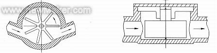
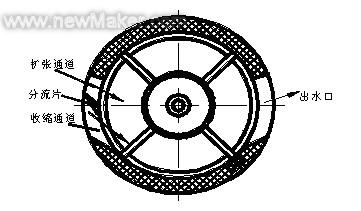
As can be seen from Fig. 3, the cross-sectional area A1 of the contraction flow path at the inlet of the impeller chamber gradually decreases along the flow direction, and the cross-sectional area A2 of the expansion flow path gradually increases. It can be known from the continuity equation of the incompressible fluid that the flow area is inversely proportional to the flow velocity. The velocity V1 of the water entering the constricted flow channel will increase, and the velocity V2 of the flow entering the expanded flow channel will decrease. From Bernoulli's equation, V1 decreases, p1 increases, V2 increases, and p2 decreases, so there is a pressure difference between the water flowing from the two channels into the impeller chamber. This pressure difference will push the water flow to a small pressure. The direction of the flow, thereby pushing the impeller counterclockwise rotation; contraction channel to increase the speed of the water into the cavity, increase its momentum, in the small flow, the impeller is greatly affected by friction between the shaft and the bearing, if the base table Without this baffle, but a single passage, the flow of water can easily flow directly from the impeller clearance instead of pushing the impeller to rotate, thereby increasing the initial flow rate.
From the above analysis, it can be seen that the geometry of the two channels is crucial for determining the direction of rotation of the impeller at the initial moment of flow. This design relies on the difference in pressure at the outlet of the two channels to cause the flow of water to flow counterclockwise in the base table cavity. The second channel outlet flow velocity V2 is greater than the first channel outlet velocity V1 and the deflection angle is greater than V1. This flow mechanism determines that the impeller must rotate counterclockwise when the water flow begins to flow.
The initial design of the impeller chamber and the shape of the guide vane is shown in Fig. 3. The front end of the guide vane is close to the outside diameter of the impeller and is a sharp angle. The angle between it and the central connection and horizontal axis is 8 degrees, and the 85°C hot water test is performed. After that, the deformation of the deflector is impaired and therefore must be improved. The improvement starts with two aspects. One is to replace the high-temperature resistant material, and the other is to change the geometry of the guide vane.
See Figure 4 for a schematic diagram of the improvement of the baffle. The cross-section of the baffle before the improvement is triangular ABC, and the improved shape is pentagon AAB'BC. A', B' are offset by 2° from the A and B points to the center line. After such modification, the cross-sectional area of ​​the baffle increases, the thickness increases, and the strength must increase correspondingly. At the same time, the tilt angle of the baffle near the center line decreases, changing the shape of the contraction channel, and the flow of water flowing through this channel will correspondingly change. 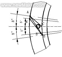
In order to further improve the performance of the base watch, the material of the impeller has also been improved. The original design of the impeller material used PPS, instead of nylon 66 + glass fiber, improved weight reduction of the impeller, and its friction with the corresponding reduction in the bearing, through the comprehensive improvement of the base table, the base table of the initial flow is reduced, Pulse equivalents increase significantly. The test results show that the initial flow rate is reduced from the original 16L/h to about 10L/h. The pulse equivalent increases by about 8%, greatly improving the performance of the watch.
In order to ensure that the equivalent pulses between the base tables are the same, in the past, the base table was often provided with adjusting parts at different positions to adjust the magnitude of the pulse equivalent. To simplify the design and improve the processability, this study was set on the radial position below the top cover of the impeller chamber. Ribs, as shown in Figure 5. By adjusting the angle β between the ribs and the direction of the water flow, the magnitude of the pulse equivalent is changed. Experiments show that this method is very sensitive and effective for adjusting the base-table pulse equivalent. Compared with other traditional methods, this method has the advantages of simple structure, good processability, and easy adjustment. 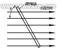
TMS3723B is a flow chip manufactured by Texas Instruments and is widely used in European heat meter products. It has 12 internal control registers and 13 data registers. By writing data into the control register, you can control the sampling frequency, comparator comparator voltage, interrupt mode, clock signal source, and the opening and closing of the inductor. Read the contents of the data register to know the status of each inductor, the number of revolutions of the impeller, and the direction of rotation of the impeller.
The actual use of the TMS3723B in the heat meter is to read the contents of the 1/4 Rotation Register and the Inductor Status Register. When the impeller rotates one revolution, the data in the 1/4 rotation register is increased by 4, and the data in the 1/4 rotation register is automatically cleared after reading out. By periodically reading the contents of the 1/4 rotation register, the impeller speed during this interval can be calculated. The inductor status register stores information such as the status of the current inductor. By reading the data in the inductor status register, it can be determined whether there is a fault in the inductor. The following is a brief description of how the TMS3723B determines the state of the inductor and counts it.
The flow sensor consists of three inductor coils, which are evenly distributed on the rotating track at an interval of 90 degrees. The lower part is an impeller, and the top surface of the impeller is coated with steam-treated damping material in a semicircular area.
Each inductor and capacitor form an LC oscillating circuit. The TMS3723B periodically charges and discharges the LC circuit so that the LC circuit generates a gradually attenuated sine signal. The comparator converts the attenuated sine signal into a digital pulse as long as the input voltage is higher than the set value. Internal value, pulse will continue to high value. 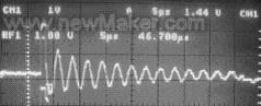
When the impeller rotates, the three inductors switch between the damped state and the undamped state in turn, and the TMS3723B judges the state of each inductor and writes the corresponding state register. One revolution counter in the TMS3723B adds 4 every revolution. The microprocessor reads the data from the TMS3723 periodically and calculates the flow based on this data.
5. Conclusions This study proposes a new method of using fluid mechanics to set a guide vane at the water inlet of the base table to change the direction of water flow and form an effective impact on the impeller. By adjusting the geometry and size of the baffle, the accuracy of the base table is improved, the flow rate at the start is reduced, and the machining process of the base table is improved. A new method of adjusting the pulsating ribs in the radial direction of the top cover of the impeller chamber to adjust the pulse equivalent of the base table is proposed. This method is simpler and more effective than other traditional methods. The use of Texas Instruments TMS3723B dedicated flow chip to ensure that the base table flow signal acquisition accuracy and reliability. The experimental test shows that, through the above comprehensive measures, the overall performance of the heat meter base table developed in this study meets the relevant requirements of the national standard and reaches the advanced level of similar foreign products.
References [1] Du Guangsheng et al., A new type of household heat meter. Proceedings of the 17th National Symposium on Hydrodynamics and 6th National Symposium on Hydrodynamics, Marine Press, 2003.12.
[2] People's Republic of China Ministry of Construction. People's Republic of China Urban Construction Industry Standard "Heat Meter". CJ128-2000, 2001-06-01 Implementation [3] State Administration of Quality Supervision, Inspection and Quarantine. The People's Republic of China national metrological verification procedures JJG. 225-2001, 2002-03-01 Implementation [4] Wang Shuxi. China's heat meter entering the new century. District heating, 2002.6
[5] Liu Yonghong et al. A smart IC card heat meter system based on MSP430F413. Electronic Technology, 2003.6
[6] Xiao Yu. Test method for heat meter. HVAC and air conditioning, 2001.5
Fig.1 Schematic diagram of a traditional single beam table
In order to eliminate the above disadvantages, this study has newly designed the heat meter base table. Its structure is shown in Fig. 2. To facilitate the processing, the inlet and outlet are designed in a straight line. This design brings great convenience to the workpiece processing, which can ensure the accuracy and greatly improve the machining efficiency. Compared with traditional base watches, the impeller-type base, the base and the metal case have increased the interference fit, and the upper cover and the base of the impeller chamber are made of high-temperature-resistant PPS to ensure that the hot water will not distort for a long time so as to ensure the heat meter. The reliability of work. Fig. 2 New single beam table
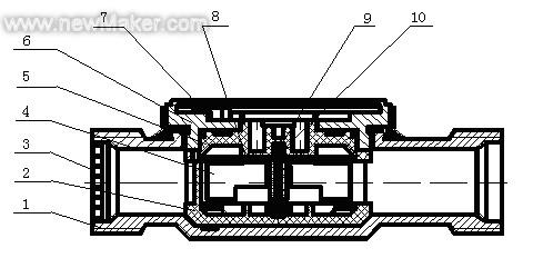
1 - Case base 2 - Wheel chamber base 3 - Rectifying grille 4 - Impeller 5 - Impeller housing upper cover 6 - Case cover 7 - Stopper 8 - Semicircular diaphragm 9 - Corundum 10 - Sleeved impeller base The shape is shown in Figure 3, in order to ensure that the water flow has a certain impact angle on the impeller blades and the water flows smoothly out of the base meter, the inlet and outlet of the impeller-type base have a certain angle with the inlet and outlet of the case, and at the same time A triangular deflector is provided at the inlet. In order to adjust the pulse equivalent, a lateral rib is arranged on the side of the impeller-shaped upper cover toward the impeller, and the purpose of adjusting the pulse equivalent is achieved by adjusting the angle between the rib and the inlet and outlet axes of the base table. Figure 3 impeller base
3. Analysis of the internal flow characteristics of the base meter When the heat meter is working, the water flows from the base table inlet to the base table via the rectifying louver, and is divided into two strands at the inlet of the impeller chamber base and enters the impeller chamber through two channels respectively. . The water flow generates a rotating motion in the impeller chamber, which drives the impeller to rotate counterclockwise and then flows out through the outlet of the impeller chamber and the outlet of the base table in turn. The non-magnetic flow sensing method used in this design is achieved through the three inductors installed above the upper cover of the impeller chamber to generate an oscillation signal when the impeller rotates. Fig. 4 Improved schematic diagram of baffle
The cross-sectional area of ​​the baffle is increased, and the narrowing of the contraction channel is known. From the continuity condition, the flow speed must increase, and the water flow will impact the impeller with greater momentum. In addition, adding a small cylindrical stopper at the top surface of the baffle can play a role in reinforcing the baffle and enhance its ability to withstand the impact of water flow. The improved deflector has been proved by experiments that under high flow rate at high temperature, the deflector will not be deformed, ensuring the normal operation of the base meter. Figure 5 Schematic diagram of adjusting ribs
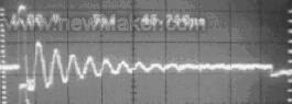
4. Collection of flow signals Traditional flow signal acquisition schemes are mostly magnetic, with poor anti-jamming capability, permanent magnet demagnetization, and the susceptibility of iron-containing impurities to adsorption. This study uses a non-magnetic sensor scheme. The specific circuit scheme is the TMS3723B scheme. Undamped Oscillation Damped Oscillation Figure 6 Undamped and Damped Oscillation Waveforms
When the inductor is located at the damping material, the sinusoidal signal will decay faster and the inductor is in a damped state due to the induction of current in the damping material. On the other hand, when the inductor is located in an undamped material, the sinusoidal signal decays slowly and the inductor is in an undamped state. TMS3723B chip can judge these two states through the internal comparator. The waveforms of the two states are shown in Figure 6.