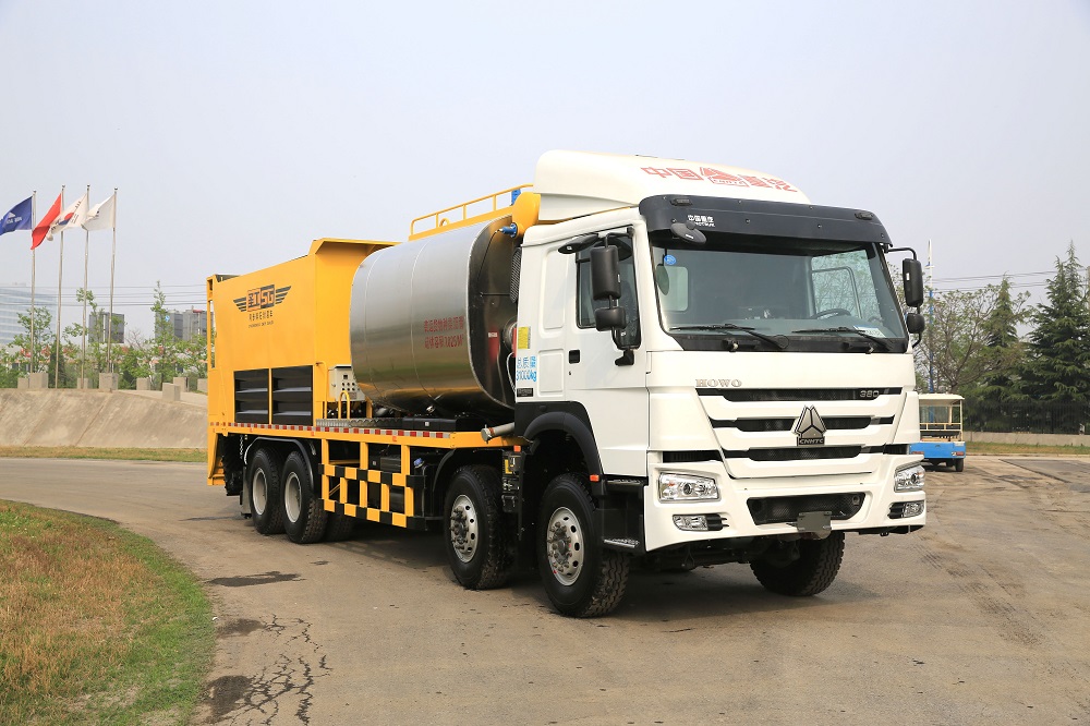
This equipment takes the
power from chassis engine,with stable and environmental performance;It adopts
rotary paddle switch and CCD camera in the inner lifting double-hopper,which
can monitor and alarm the level of aggregates in the hopper to improve the
bearing capacity,stability and reliability.It can realize operation in
height-limit condition,such as bridges and culverts.It adopts camber chip
distributing device to improve the evenness.It uses stable dedicated controller
to control the whole electric system,rear high-definition infrared cameras
monitor the whole operation,which improve the working environment and
efficiency.
Emission standards: Euro V
Chassis motor power: 276kW/380hp
Main Features
Lift Type Synchronous Chip Sealer Lift Type Synchronous Chip Sealer,Synchronous Asphalt Chip,Computerized Synchronous Chip Sealer,Road Synchronous Chip Sealer Henan Gaoyuan Road Maintenance Equipment Co., Ltd. , https://www.sgroadmachinary.com
1. Error introduced by improper installation of WRN thermocouple
For example, the location and insertion depth of the thermocouple can not reflect the true temperature of the furnace, in other words, the thermocouple should not be installed too close to the door and the heating place, the depth of insertion should be at least 8 to 10 times the diameter of the protection tube; The gap between the protective sleeve of the thermocouple and the wall is not filled with heat insulation material, so that the heat in the furnace overflows or the cold air invades. Therefore, the gap between the thermocouple protection tube and the wall hole of the thermocouple is blocked with heat insulating material such as fireproof mud or asbestos rope to avoid cold and heat. Convection of air affects the accuracy of temperature measurement; the thermocouple cold junction is too close to the furnace body to make the temperature exceed 100°C; thermocouples should be installed as far as possible to avoid strong magnetic fields and strong electric fields, so thermocouples and power cables should not be installed in the In the same conduit to avoid introducing interference caused by errors; thermocouple can not be installed in the area where the measured medium rarely flows. When using a thermocouple to measure the temperature of the gas in the tube, the thermocouple must be installed against the flow velocity, and fully in contact with the gas .
2. Error introduced by WRN thermocouple thermal inertia
Because of the thermal inertia of the thermocouple, the indicator value of the instrument lags behind the change in the measured temperature, and this effect is particularly pronounced in fast measurements. Therefore, thermocouples with thinner thermocouples and smaller diameters should be used as much as possible. When the temperature measurement environment permits, the protection tube can even be removed. Due to the measurement hysteresis, the amplitude of the temperature fluctuation detected by the thermocouple is smaller than the amplitude of the fluctuation of the furnace temperature. The larger the measurement lag, the smaller the amplitude of the fluctuation of the thermocouple and the greater the difference from the actual furnace temperature. When a thermocouple with a large time constant is used for temperature measurement or temperature control, although the temperature displayed by the instrument fluctuates little, the actual furnace temperature may fluctuate greatly. In order to accurately measure the temperature, a thermocouple with a small time constant should be selected. The time constant is inversely proportional to the heat transfer coefficient and is proportional to the diameter of the hot end of the thermocouple, the density of the material, and the specific heat. To reduce the time constant, in addition to increasing the heat transfer coefficient, the most effective method is to minimize the size of the hot end. . In use, a protective sleeve with a thin wall and a small internal diameter is generally used with good thermal conductivity. In the more precise temperature measurement, a bare wire thermocouple without a protective sleeve is used, but the thermocouple is easily damaged and should be promptly corrected and replaced.
3, WRN thermocouple thermal resistance error
At high temperatures, such as a layer of coal ash on the protective tube, dust attached to it, the thermal resistance increases, hinder the conduction of heat, then the temperature indication is lower than the true value of the measured temperature. Therefore, the outside of the thermocouple protection tube should be kept clean to reduce errors.
WRN thermocouple
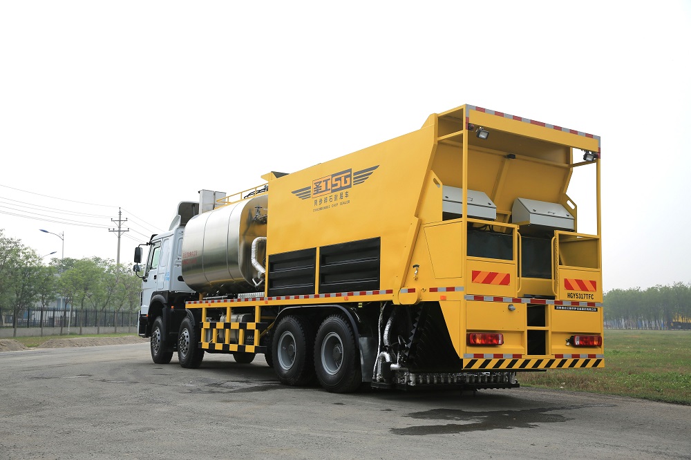
HGY5317TFC Chip Spreader with asphalt binder is specially designed for asphalt mixing and spreading purposes in road and bridge maintenance projects. Developed from KT0608 and KT0610, this new equipment has something that the previous models fail to offer: it is endowed with stronger processing capability for the tank volume is increased to 8m³ and the volume of hopper grows to 14m³. The bitumen spreading machine is capable of spraying roughly aggregate of 8㎡ without lifting the hopper, which allows the equipment to work in low-height conditions.
HGY5317TFC chip spreading machinery drives stably, sprays material uniformly, and is affordable. A powerful mixing device is available to ensure the rubberized asphalt is not easy to get precipitated or segregated.
Technical Parameters
Model: HGY5317TFC
Chassis model: HOMO ZZ3317N4667E1 from CNHTC
Asphalt spray volume: 0.2-3.0kg/㎡
Aggregate spray volume: 2-22L/㎡
Asphalt heating speed: 20℃/h
Optimum construction speed: 3-6km/h
Chip size: 3-30mm
Tank volume: 8500L
Spray width: 4200mm
Hopper volume: 14m³
Material: modified bitumen, hot asphalt, rubberized asphalt, and emulsified asphalt
Total weight: 31000kg
Dimension: 11950×2500×3860mm (L×W×H)
1. The asphalt sprayer adopts a special chassis which is in conformity with the Euro V standards, featuring strong carrying capability, low oil consumption, and easy operation
2. The patented hydraulic servo technology provides powerful driving force for the system
3. The bitumen spreading machine employs intelligent control system, radar speed tester, monitor, and both automatic and manual operation system. Only one driver is needed to accomplish the distribution job
4. Pipes for carrying bitumen are coated with heat transfer oil to ensure that all of the machine parts run smoothly and don't have to be cleaned
5. The 3 anti-collision foldable sprinkler heads are of high precision and uniformity
6. The imported pump for high-viscosity asphalt meets various working conditions
7. A unique aggregate feeding and distribution system ensures the materials are sprayed uniformly, consecutively and stably
8. Different spray nozzles are controlled independently and can work jointly with each other freely
9. HD camera is equipped at back of the road maintenance vehicle for effective monitor and control
10. The patented bitumen tank with large volume can be heated in a short time and works to maintain the temperature of the materials. Stability of the bitumen is largely improved by the mixing device


The correct use of WRN thermocouple can not only accurately obtain the value of temperature, ensure the product is qualified, but also can save the material consumption of thermocouple, saving both money and product quality. Improper installation, errors in thermal conductivity and time lag, etc., are major errors in the use of thermocouples.