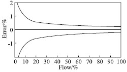
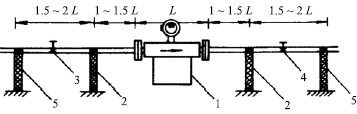
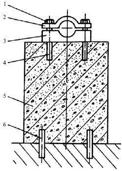
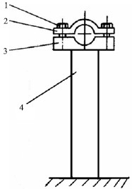
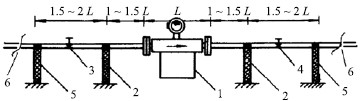
With the constant acceleration of industrial development, the requirements for flowmeters are also increasing. Tianchen Bo Rui mass flowmeter is a high standard mass flow meter that can measure fluid quality, temperature and density, and can also calculate the flow volume. In the practical application process, the accuracy of the mass flow meter is extremely high. Therefore, in the practical process, the accuracy of the mass flow rate must be improved. Start with the principle of a mass flow meter. First, the working principle of Coriolis mass flowmeter Tianchen Bo Rui mass flowmeter uses the measuring tube (also known as vibrating tube) two-half vibration frequency phase ratio is proportional to the mass flow to measure the mass flow, using the measurement tube resonant frequency and the measured density of the medium in the pipe to determine the relationship between density. The Coriolis mass flowmeter also derives the volume flow qv from the two basic parameters mass flow qm and density p. Second, the factors affecting the practical accuracy of Coriolis mass flowmeter The Coriolis mass flowmeter is an electromagnetically-driven mechanical vibration type flow measurement instrument, and the material constituting the measurement tube of the flowmeter is affected by the pressure and temperature of the process medium. The flow measuring tube installed in the pipeline (also called the flow vibrating tube) is affected by the mechanical vibration, mechanical stress, and mechanical torque of the factory pipeline. In addition, the error characteristic exhibited by the Coriolis mass flowmeter itself presents a "horn" rather than a flat straight line at different flow rates. In view of the above reasons, measures to improve the practical accuracy of Coriolis mass flowmeters are: 1) For the actual process parameters of the Coriolis mass flowmeter, a "personalized standard" is applied to the flowmeter so that the actual measurement error of the Coriolis mass flowmeter can be realized within a certain range of actual usage flow points. (difference from the standard value) tends to zero; 2) The installation of a good Coriolis mass flow meter to reduce or eliminate the influence of mechanical stress, mechanical torque and mechanical vibration on the use of the flowmeter; 3) Consider the influence of process pressure and temperature on the measurement accuracy of Coriolis mass flowmeters; 4) Turn off the use of a good Coriolis mass flow meter. Third, the realization of Coriolis mass flow meter practical accuracy of the program 3.1 Implementation of a "personalized standard" program to achieve near zero error in flow measurement Coriolis mass flowmeter error formula:      In the formula: E allowed - the allowable error of the flowmeter; E0—the accuracy of the flowmeter; Qz—the zero drift of the flowmeter; q Measurement—The current measurement of the flow meter. This shows that the error characteristic curve of Coriolis mass flowmeter is shown in Figure 1.    Fig. 1 Error characteristic curve of Coriolis mass flowmeter For Coriolis mass flowmeter error characteristics, combined with the actual use of technology, Coriolis mass flowmeter only work in a relatively small flow range, which can be managed to make the flowmeter in a certain range of the actual use of the flow point The measurement error within (usually control this range is ± 20% of the actually used flow point) tends to zero, for which the liquid flow standard device can be used to set the flow verification point according to the national quality flow meter verification protocol (JJG1038-2008), and Calibrate the ±20% range of the actually used flow point (at least three points: 80% Q actual, Q actual, 120% Q actual) to achieve the “personalized standard†of the mass flow meter. Its main purpose is to Let its standard result meet the requirements of the quality flowmeter verification protocol, and let the mass flowmeter be within ±20% of the actual use flow point. The measurement error of the sampling standard at three points tends to zero, especially to achieve The measurement error of the actually used flow point (the difference between the flow meter indication and the standard value of the standard device) is zero. Only in this way can the work of the mass flow meter “personalization standard†be completely completed. According to the above assumptions, a "mass standard" is performed for a mass flowmeter numbered. The flow point from the factory to the flowmeter is: 21.7t/h, and the maximum flow rate is 43.6t/h. According to the requirements of the national quality flow meter verification protocol (JJG1038-2008), the verification error of the test result at 21.7 t/h is: -0.153%. Judging from the above data, the measurement accuracy of the mass flowmeter at the practical use point of 21.7t/h flow rate is not very high. Therefore, according to the above data, the flowmeter is calibrated, and its flow calibration coefficient is increased by 0.153%, and then According to the "individual standard" method, the flow meter is standardized. The error of the re-standard result at 21.7 t/h is: 0.002%. Through the above-mentioned practice, the Coriolis mass flowmeter is effectively implemented as a “personalized standard†so as to achieve a flow measurement approaching zero error. This practical technology is worth promoting. 3.2 Start with the installation process to eliminate the impact of mechanical factors on the use of the flowmeter Coriolis mass flowmeter is a kind of mechanical vibration flowmeter. To ensure the high accuracy of the actual use of the flowmeter, you should try to eliminate vibration, stress, torque and other mechanical factors in the installation process of Coriolis. Effect of mass flow meter usage. 3.2.1 Plan to Eliminate Mechanical Vibration At the site where Coriolis mass flow meters are actually used, mechanical vibration is an objective reality. Because it is a mechanical vibration type flow measurement instrument, then there is a vibration system of the flowmeter itself will be affected by the external vibration system, whether there is a way to make the vibration of the flowmeter's own vibration system not transmitted to the outside world, and at the same time it does not The vibration of the external vibration system is transmitted to the flowmeter vibration system, and the vibrations of the two vibration systems are managed to be isolated from each other, so that the effects of the mechanical vibration on the measurement can be eliminated. After practice, for the occasion with strong vibration, installing the Coriolis mass flowmeter in Figure 2 can eliminate the influence of vibration on the measurement.    1-sensor; 2-first group support; 3,4-stop valve; 5-second group support    Figure 2 Distribution of pipe supports If it is unavoidable to install the sensor in a strong vibration area, it is better to use a pipe support with good vibration isolation. Pipe supports should have sufficient stiffness and quality. The specific approach is: the lower end of the support must be fixed on a stable basis, the upper end and the pipe clamp to support the process pipeline, but do not use the watch body to support the pipeline and auxiliary equipment, including the sensor itself. After the pipe is supported, the entire sensor (box and flange) should be left free. The support should be symmetrically distributed around the sensor. The distance from the center should be 1 to 1.5 times the length of the sensor. The stop valve is installed outside this group of supports. For larger diameter sensors, a symmetrical set of supports (shown in Figure 2) can be added to the outside of the shutoff valves on both sides. The lower end of the support is fixed on the ground and must be a cement foundation. The more stable the foundation, the more reliable the support, the better its vibration damping. When space is allowed, it is recommended to use a cement pier with a clamp. The structure of the cement pier is shown in Figure 3. The axis of the support hole of the pipe clamp should be in a horizontal position, and the height of the support should be a horizontal straight line of the process pipeline. Clamping the process pipe with clips helps to attenuate potentially interfering vibrations (Figure 4).      1- Fastening nut; 2-upper clamp; 3-lower clamp; 4- anti-movement bolt; 5-Cement body; 6-foot bolt   Figure 3 Vibration-resistant cement pier      1- Fastening nut/screw; 2-upper clamp; 3-lower clamp; 4-support column    Figure 4 tube card and support 3.2.2 Scheme to Eliminate Mechanical Stress and Mechanical Torque Although Coriolis mass flowmeter manufacturers have taken steps to reduce the impact of mechanical stress and mechanical torque on the mass flowmeter in real-world applications, the "stressless" installation is a Coriolis mass flowmeter sensor installation. The prerequisites that must be observed are also the biggest differences from other flow sensor installations. Only by installing “no stress and no torque†can the actual application process of Coriolis mass flowmeter be accurate and reliable. After practice, an "integrated installation" proposal was put forward: the sensor was coaxial with the process pipeline, and the sensor flange installation dimensions were in line with the reserved dimensions of the process pipeline. During the installation, the connectors were evenly and symmetrically applied (if conditions were available Torque wrench) to make the connection between the flow sensor and the front and rear connecting pipe without torque. The following measures can be adopted in specific practice: By using the exact dimensions of the surface-to-surface of the process connector, the sensors to be installed must first be aligned and connected coaxially with the upstream and downstream pipelines (each of which has an appropriate length). Pay attention to maintain the uniform force of the connector, and then install the upper and lower stop valves and their outer piping (each with a short section). Pre-connect these as a whole, and then prefabricate this integral lifting on the 2 and 5 support columns, and tighten the tube clamps. Finally, the six parts in Figure 5 are welded to the process master wire. During the welding process, first spot welds should be aligned to make sure that they are evenly stressed. Finally, full welding is performed at the six positions. In addition, if the corrugated retractor can be installed in the “2~5†sections before and after the mass flowmeter, mechanical stress or torsion can be completely eliminated, and it is beneficial to disassembly and assembly of the periodic inspection. Practice has proved that this is an effective “no-stress†installation scheme. The Coriolis mass flowmeter installed according to this scheme also has obvious advantages when it is checked and disassembled. This solution can well eliminate the influence of mechanical stress and mechanical torque and ensure the accurate and reliable measurement results of Coriolis mass flowmeters.    1-sensor; 2-first group support; 3,4-stop valve; 5-second group support    Figure 5 Welding of Pipe Supports 3.3 Effect of process pressure and temperature on metering accuracy When the Coriolis mass flowmeter is calibrated at the factory, it is impossible for the pressure and temperature of the calibration medium to be consistent with the pressure and temperature of the actually used medium. How to eliminate the influence of pressure and temperature on the measurement accuracy? The accuracy is not high. On occasions, reference can be made to the correction factor of the pressure and temperature provided by the manufacturer to the user (referred to as the coefficient correction method). In the case of high accuracy requirements, the “standard flow device (simulated pressure range: 0.3~1.5 MPa) that can simulate the pressure of on-site conditions at the measurement center station of Yangzi Petrochemical Company†is used to perform “on-site process pressure†for the mass flowmeter. Simulation Standards." Current Coriolis mass flowmeters from companies such as Emerson and E+H have minimal impact on metering accuracy and can be ignored. The main consideration is the effect of actual process pressure on metering. 3.4 Turn off the use of a good Coriolis mass flow meter The "personalized accuracy" and "accurate on-site pressure simulation" of the Coriolis mass flowmeter actually match the mass flowmeter with the conditions of the actual application. The ultimate goal is to make the mass flowmeter suitable for metering. The actual situation of the object to ensure accurate and reliable measurement results. Starting from the installation process, the mass flow meter has a solid foundation and a good “living environment†to try to eliminate the influence of mechanical vibration, mechanical stress, and mechanical torque on the use of Coriolis mass flow meters. After completing the standard of the mass flowmeter, after installation, how to verify whether the installation meets the requirements and how to ensure the high accuracy of the actual use, it is particularly important to turn off the Coriolis mass flowmeter. The specific contents of the investment include: verification and verification or standard certificate, confirming the configuration of the flowmeter, confirming the electrical wiring of the flowmeter, power supply, grounding, confirming whether the installation conditions are normal, and performing “zero calibrationâ€. Based on the above measures and plans, the company implemented standards ("personalized standards" and "simulated pressure standards"), installation, and commissioning of a CMF400 mass flow meter for naphtha metering. After more than three months Operational assessment and measurement confirmation, the actual transfer of the flowmeter error has been kept within 0.034%, to achieve a high degree of actual measurement. Practice has proved that the technical measures and programs provided by this article are effective. Fourth, the conclusion In short, in the practical application of mass flowmeters, certain standards must be met. During the process of selection, standardization, installation, and commissioning, the process control of each link must be controlled and the key points in the application process must be understood. detail. By doing this, we can improve the accuracy of the mass flowmeter. Huadiao Wine,Hua Diao Wine Aged 15Years,Naturelly Shaoxing Yellow Rice Wine,Gu Yue Long Shan Yellow Wine ZHEJIANGGUYUELONGSHAN SHAOXING WINE CO.,LTD. , https://www.chinashaoxingwine.com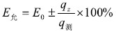
5A grade Huangjiu is adopted for aged wine,i.e. A grade raw materials, A grade timing, A grade pottery jar, A grade storage and A grade brewers. Using Huangjiu of the most representative years as base, aged wine is bottled in green porcelain for banquet and gift-giving. Glass-bottled-wine is mainly used for 3-5 years of ordinary wine, with superior cost performance, suitable for people who drink at home frequently.